Remote Asset Integrity Monitoring for Pipelines and Cathodic Protection
A comprehensive guide to remote pipeline monitoring, cathodic protection monitoring, AC interference, electrical isolation and the technologies helping operators understand the condition of critical infrastructure.
Pipelines and other buried metallic assets are expected to operate safely and reliably for decades, often across hundreds or thousands of miles and through environments that can be difficult, expensive or hazardous to access.
Protecting these assets requires more than installing a corrosion-control system and periodically checking that it is still operating.
Remote asset integrity monitoring allows pipeline operators, corrosion engineers and cathodic protection professionals to continuously or periodically collect important integrity data from strategically selected locations. This information can be transmitted remotely, analysed over time and used to identify changing conditions before they develop into more significant integrity concerns.
For cathodically protected pipelines, remote monitoring can extend far beyond a simple voltage reading. Modern monitoring technology can be used to evaluate pipe-to-soil potentials, cathodic protection performance, instant-off potentials, coupons, electrical bonds, isolation points, AC interference and other electrical conditions.
This guide explains what remote asset integrity monitoring is, how the technology has evolved, what can be monitored and how remote data can support better pipeline integrity decisions.
What Is Remote Asset Integrity Monitoring?
Remote asset integrity monitoring is the automated collection, transmission and analysis of measurements relating to the condition, protection or performance of an asset without requiring a technician to physically visit the monitoring location each time a measurement is needed.
For pipelines, remote monitoring may include operational measurements such as pressure, temperature and flow. However, it can also encompass specialist integrity measurements associated with corrosion control, cathodic protection (CP), electrical isolation and AC or DC interference.
A remote monitoring location can effectively operate as an intelligent, permanently connected test point.
Instead of a technician travelling to a location, connecting test equipment, taking a measurement and manually recording the result, permanently installed monitoring equipment can collect measurements automatically.
Depending on the application, these measurements can then be transmitted to a remote platform where authorised users can:
Review current readings
Analyse historical trends
Compare measurements over time
Identify abnormal conditions
Establish acceptable operating thresholds
Receive alerts when conditions change
Investigate AC and DC electrical behaviour
Prioritise physical inspections
Identify locations requiring further investigation
Build a more complete picture of asset behaviour
The important distinction is that remote monitoring is not simply about collecting more data.
Its real value lies in turning field measurements into useful integrity information.
Key term – Remote asset monitoring: The automated observation of equipment or infrastructure from a location other than the physical asset itself, typically using sensors, data acquisition equipment and communications technology.
Key term – Pipeline integrity monitoring: The measurement and assessment of conditions that could affect the continued safe operation of a pipeline, including corrosion, cathodic protection effectiveness and electrical interference.
Why Do Pipelines Need Integrity Monitoring?
Steel is strong, reliable and economical, making it an ideal material for pipelines. However, when steel is exposed to an electrolyte such as soil or water, electrochemical reactions can cause it to corrode.
Buried and submerged pipelines are therefore commonly protected using several complementary approaches.
Protective coatings provide a physical barrier between the steel and the surrounding environment.
Cathodic protection electrochemically protects areas of exposed steel where the coating may be absent, damaged or deteriorated.
Electrical isolation helps control where cathodic protection current flows and establishes defined electrical boundaries within the pipeline system.
Inspection and monitoring help establish whether these protective measures continue to operate as intended.
No pipeline coating should simply be assumed to remain perfect throughout the operating life of an asset. Installation damage, ageing, soil movement, mechanical damage and other mechanisms can create areas where steel becomes exposed.
Cathodic protection can protect these areas.
Monitoring helps determine whether that protection remains effective.
Understanding Corrosion
Corrosion is fundamentally an electrochemical process.
For corrosion to occur, a corrosion cell typically contains four essential components: an anode, a cathode, an electrolyte and a metallic path.
Anode
The anode is the location at which oxidation and metal loss occur.
For iron, the anodic reaction can be represented as:
Fe → Fe²⁺ + 2e⁻
Iron atoms lose electrons and enter the surrounding electrolyte as ions.
Cathode
The cathode is the location where reduction reactions occur.
The cathodic area receives electrons and does not experience the same anodic metal dissolution.
Electrolyte
An electrolyte is an electrically conductive environment through which ions can move.
For a buried pipeline, the surrounding soil and groundwater form the electrolyte.
Metallic Path
The pipeline itself provides a conductive path through which electrons can move between different areas of the structure.
Where these conditions exist, electrochemical corrosion cells can form on the pipeline surface.
[IMAGE: Corrosion Cell Diagram]
Key term – Anode: The area of an electrochemical cell where oxidation occurs and metal loss can take place.
Key term – Cathode: The area of an electrochemical cell where reduction occurs. Cathodic protection is designed to make the protected structure behave as a cathode.
Key term – Electrolyte: An ionically conductive environment, such as soil or water, through which ionic current can flow.
What Is Galvanic Corrosion?
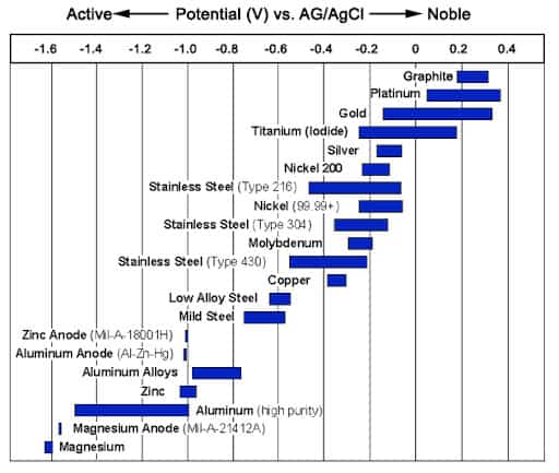
Galvanic corrosion can occur when electrically connected metals with different electrochemical potentials are exposed to a common electrolyte.
The more active, or less noble, metal tends to become anodic and corrodes preferentially, while the more noble material behaves cathodically.
The severity of galvanic corrosion can be influenced by factors including:
The potential difference between the metals
The relative anodic and cathodic surface areas
Electrolyte conductivity
Oxygen availability
Temperature
Environmental conditions
The same fundamental electrochemical principle also provides the basis for one form of cathodic protection: sacrificial-anode cathodic protection.
[IMAGE: Galvanic Corrosion Diagram]
Key term – Galvanic corrosion: Preferential corrosion that can occur when electrically connected metals with different electrochemical potentials are exposed to a common electrolyte.
What Is Cathodic Protection?
Cathodic protection (CP) is an electrochemical corrosion-control method used to reduce corrosion by supplying electrons to a metallic structure so that the protected structure behaves as the cathode of an electrochemical cell.
Cathodic protection is widely used to protect:
Oil and gas transmission pipelines
Water pipelines
Buried process piping
Storage tanks
Marine structures
Offshore infrastructure
Ship hulls
Piling systems
Reinforced concrete structures
Other buried or submerged metallic assets
There are two principal forms of cathodic protection: sacrificial-anode cathodic protection and impressed-current cathodic protection.
[IMAGE: Basic Cathodic Protection Concept]
Sacrificial-Anode Cathodic Protection
A sacrificial-anode cathodic protection system, sometimes abbreviated to SACP, electrically connects the protected structure to a metal that is naturally more electrochemically active.
Common sacrificial-anode materials include:
Magnesium
Zinc
Aluminium
The sacrificial material corrodes preferentially, supplying protective current to the structure.
Advantages of Sacrificial-Anode Systems
Sacrificial-anode systems can offer several advantages:
No external electrical power supply
Relatively simple design
Self-regulating behaviour
Low maintenance requirements
Suitability for smaller or distributed assets
Reduced potential for some forms of stray-current interference
Limitations of Sacrificial-Anode Systems
Their available output is limited by the natural electrochemical potential difference between the anode and the protected structure.
Performance can also be affected by environmental resistivity, and sacrificial systems may not provide sufficient current for some large or long-distance assets.
Key term – SACP: Sacrificial Anode Cathodic Protection uses a more electrochemically active metal to provide protective current to another metallic structure.
Impressed-Current Cathodic Protection
Impressed-current cathodic protection (ICCP) uses an external DC power source and an anode system to provide protective current.
A transformer-rectifier, often referred to simply as a rectifier or TR, is commonly used to convert an incoming AC electrical supply into the DC current required by the cathodic protection system.
ICCP is particularly suited to large structures and long pipelines because the current output can be adjusted according to system requirements.
Advantages of ICCP
Typical advantages include:
Higher available current output
Suitability for long pipelines
Ability to protect large coated structures
Adjustable output
Suitability for higher-resistivity environments
Challenges of ICCP
ICCP systems also introduce additional considerations:
An external power source is required
Transformer-rectifiers require monitoring and maintenance
Incorrect settings can affect CP performance
Electrical interference needs to be considered
System behaviour can change as coating and environmental conditions change
Key term – ICCP: Impressed Current Cathodic Protection uses an externally powered DC source and an anode system to provide protective current.
Key term – Transformer-rectifier: Equipment that converts AC electrical power into the DC electricity used by an impressed-current cathodic protection system.
Why Does Cathodic Protection Need to Be Monitored?
Cathodic protection is not an “install and forget” technology.
The electrical environment surrounding a pipeline can change throughout its operating life.
Potential changes can result from:
Ageing or damaged coatings
Seasonal soil conditions
Changes in soil moisture
Changes to neighbouring infrastructure
New pipelines or utilities
Changes in power transmission infrastructure
Changes to rectifier output
Electrical shorts
Loss of electrical isolation
Failed or altered bonds
DC stray current
AC interference
Changing electrical loads
Deterioration or failure of CP components
A satisfactory measurement taken several months ago does not necessarily describe current conditions.
Cathodic protection monitoring provides the information needed to understand whether the corrosion-control system continues to perform as intended.
How Has Remote Pipeline Monitoring Evolved?
Remote asset monitoring has developed alongside major advances in industrial automation, electronics, telecommunications and data analysis.
The transition has been gradual, moving from predominantly manual inspection towards increasingly connected and intelligent monitoring systems. Your historical material traces modern pipeline remote monitoring back to the development of SCADA systems in the 1960s, followed by advanced sensors, wireless communications and IoT technologies.
Traditional Manual Inspection
Historically, cathodic protection technicians travelled to individual test stations and rectifiers to obtain measurements manually.
Manual inspection remains an important part of modern integrity programmes. However, a manual measurement represents conditions at one particular moment in time.
If an electrical event occurs at night, during a utility load change or several weeks between inspections, it may never be recorded.
Manual measurements can also introduce inconsistencies caused by differences in:
Technician methodology
Instrumentation
Reference electrode placement
Environmental conditions
Measurement timing
Data recording
Remote monitoring addresses some of these limitations by repeatedly collecting data using a consistent measurement process. Your source material specifically identifies consistency, reduced human variation and reduced travel to remote locations as significant advantages.
SCADA and Centralised Monitoring
The emergence of Supervisory Control and Data Acquisition (SCADA) systems from the 1960s onwards began to change how geographically distributed pipeline infrastructure could be operated.
Early SCADA systems allowed operators to monitor and control certain pipeline functions from centralised locations.
These systems were primarily focused on operational variables such as:
Pressure
Flow
Temperature
Pump operation
Valve positions
Early systems were constrained by the available sensors, communications infrastructure, computing technology and cost.
Key term – SCADA: Supervisory Control and Data Acquisition is an industrial control architecture used to collect information from, and potentially control, geographically distributed equipment.
Digital Sensors and Wireless Communications
Advances in electronics progressively reduced the size, cost and energy requirements of monitoring equipment.
Digital data acquisition enabled more repeatable measurements and much larger datasets.
At the same time, expanding wireless and cellular communications made it possible to transmit information from locations that previously required proprietary communications infrastructure or physical data collection.
The Internet of Things
The development of the Internet of Things (IoT) accelerated remote asset monitoring.
Connected field devices could increasingly:
Acquire a measurement
Process information locally
Transmit information wirelessly
Store data remotely
Make information accessible through a web-based platform
This enabled monitoring to become more distributed and scalable.
Key term – IoT: The Internet of Things describes connected physical devices capable of collecting, processing and exchanging data through communications networks.
From Remote Measurement to Remote Analysis
One of the most important developments has been the transition from remote measurement towards remote analysis.
Early monitoring devices could essentially act as automated meters.
They measured a parameter and transmitted a number.
More advanced monitoring asks additional questions:
What makes up the measured signal?
Is the electrical condition AC or DC?
Is an AC component external interference or rectifier ripple?
Does the signal change when the CP rectifier is interrupted?
Is the condition persistent, intermittent or transient?
Has its behaviour changed compared with previous weeks or months?
This transition from simply measuring conditions to helping interpret them is becoming central to modern remote asset integrity monitoring.
What Parameters Can Be Remotely Monitored on a Pipeline?
A modern remote cathodic protection monitoring programme can potentially monitor considerably more than a single pipe-to-soil potential.
Depending on the monitoring location and objective, parameters can include:
Pipe-to-soil potential
Structure-to-electrolyte potential
ON potential
Instant-off potential
Native potential
Reference electrode measurements
Rectifier output voltage
Rectifier output current
Coupon potential
Coupon current
DC current density
AC voltage
AC current
AC current density
Bond current
Electrical isolation
Stray-current conditions
AC/DC interference
Waveform characteristics
Frequency components
Device status
Battery condition
Communications status
This multi-parameter approach is important because pipeline integrity cannot always be understood from one measurement alone.
Your remote-monitoring materials similarly identify ON potentials, instant-off measurements, coupon testing, bond monitoring, isolation monitoring and AC monitoring as core functions.
Pipe-to-Soil Potential Monitoring
A pipe-to-soil potential, also called a structure-to-electrolyte potential, measures the electrical potential difference between a buried pipeline and a reference electrode in contact with the surrounding electrolyte.
It is one of the fundamental measurements used in cathodic protection.
Remote measurement allows a particular location to be monitored repeatedly and consistently.
Instead of a single measurement, operators can create a historical record showing whether the potential is:
Stable
Gradually changing
Periodically fluctuating
Responding to rectifier changes
Responding to environmental changes
Being influenced by another electrical source
This historical context can make a measurement considerably more useful.
Key term – Pipe-to-soil potential: The electrical potential measured between a buried pipeline and a reference electrode in contact with the surrounding soil or electrolyte.
Key term – Reference electrode: An electrode with a stable electrochemical potential used as a reference when measuring another structure's potential.
ON Potential Monitoring
An ON potential is measured while the cathodic protection system remains energised.
It provides valuable information about pipeline electrical conditions, although the reading can include voltage drop through the surrounding electrolyte associated with current flow.
For this reason, ON potentials and instant-off potentials provide different information.
Remote monitoring makes ON potential measurements particularly useful when they are collected consistently and trended over time.
Key term – ON potential: A structure-to-electrolyte potential measured while cathodic protection current sources remain energised.
Instant-Off Potential Monitoring
An instant-off, or I-OFF, measurement is obtained immediately after cathodic protection current is interrupted.
The objective is to reduce the influence of voltage drop through the electrolyte and obtain a measurement that more closely represents the pipeline's polarised potential.
Coordinating instant-off measurements across large pipeline networks can traditionally require considerable planning.
Remote monitoring can simplify repeated and coordinated measurements while also creating opportunities to compare electrical behaviour immediately before and after CP interruption.
Key term – Instant-off potential: A pipeline potential measured immediately after interruption of cathodic protection current and before significant depolarisation occurs.
Key term – IR drop: Voltage drop created as electrical current flows through resistance in the measurement path.
Coupon Monitoring
A corrosion coupon is a small piece of metal exposed to the surrounding electrolyte and electrically associated with the pipeline.
Coupons can simulate a known area of exposed pipeline steel, such as a coating defect.
Because the exposed surface area is known, measured current can be converted into current density.
Remote coupon monitoring can therefore provide information relating to:
Coupon potential
Protective current
DC current density
AC current density
Changes in electrical exposure over time
This can become particularly important when investigating AC interference.
Key term – Corrosion coupon: A deliberately exposed metallic test element used to simulate a coating defect and support electrochemical measurements.
Key term – Current density: Electrical current divided by the surface area through which it passes, commonly expressed in amperes per square metre (A/m²).
Electrical Isolation Monitoring
Effective cathodic protection relies on controlled electrical boundaries.
An isolation joint, flange isolation system or other dielectric device may be used to electrically separate pipeline sections or prevent CP current from flowing onto another metallic structure.
Electrical isolation helps establish predictable CP zones and control where protective current flows. Your cathodic protection material highlights isolation as important for preventing uncontrolled CP-zone current flow, stray-current interactions and misleading potential measurements.
If isolation becomes electrically shorted or otherwise compromised, potential consequences can include:
Increased CP current demand
Loss of defined CP zones
Misleading potential measurements
Current flowing onto neighbouring structures
Unstable CP behaviour
Increased electrical interference
Remote monitoring can compare electrical conditions on opposite sides of an isolation point and identify changes in behaviour.
Key term – Electrical isolation: Intentional electrical separation between metallic structures or pipeline sections so that electrical current can be controlled.
Key term – Isolation joint: A pipeline joint incorporating a dielectric barrier that electrically separates adjoining pipeline sections.
Bond Monitoring
Not every electrical connection between structures is undesirable.
Some pipeline systems require deliberate electrical bonds.
A bond may be installed to:
Manage electrical interference
Connect structures intentionally
Provide a defined current path
Support interference mitigation strategies
A failed, disconnected or changing bond can alter electrical conditions across a wider pipeline system.
Remote monitoring can therefore be used to observe bond current and identify unexpected changes in bonded structures.
Key term – Electrical bond: An intentional electrical connection between two structures designed to provide a controlled path for electrical current.
Cathodic Protection Rectifier Monitoring
Transformer-rectifiers are critical components of impressed-current cathodic protection systems.
Remote rectifier monitoring can include:
DC output voltage
DC output current
Operational status
Changes in output
Abnormal behaviour
Electrical characteristics associated with rectification
At its simplest, monitoring can identify that a rectifier has stopped operating.
More sophisticated monitoring can help engineers understand how the rectifier is behaving and how its output is influencing the protected pipeline.
AC Interference Monitoring on Pipelines
One of the increasingly important areas of pipeline integrity management is alternating-current interference monitoring.
Pipelines and high-voltage electrical transmission infrastructure can share or intersect the same utility corridors.
Where pipelines run close to energised transmission systems, electrical energy can be coupled onto the pipeline.
The resulting AC interference can depend on multiple factors, including:
Transmission-line configuration
Electrical load
Separation distance
Length of parallel exposure
Pipeline geometry
Pipeline coating condition
Soil resistivity
Grounding arrangements
Phase configuration
Local operating conditions
Your technical material describes AC interference as an increasingly important pipeline-integrity challenge, particularly where buried pipelines coexist with high-voltage transmission infrastructure.
Why Is AC Interference Important?
AC exposure can create both personnel-safety concerns and pipeline-integrity concerns.
Personnel Safety
AC voltage on a pipeline can create touch-potential concerns at accessible metallic components.
Understanding electrical conditions at these locations is therefore important for personnel who may come into contact with the pipeline or connected infrastructure.
Pipeline Integrity
AC passing between a pipeline and the surrounding electrolyte through a small coating defect can produce concentrated AC current density.
Under certain conditions, this can contribute to localised corrosion.
Key term – AC interference: Unwanted alternating electrical energy coupled onto a pipeline from an external AC source.
Key term – AC-induced corrosion: Localised corrosion associated with alternating current entering or leaving a buried metallic structure through exposed areas such as coating defects.
Why AC Voltage Does Not Tell the Whole Story
Measuring AC voltage can indicate that an alternating electrical potential is present on a pipeline.
However, voltage alone does not necessarily describe the complete corrosion risk.
An important additional parameter is AC current density.
Current density considers how much current is flowing through a particular exposed surface area.
A relatively small coating defect can concentrate electrical current through a very small area.
This is one reason coupon monitoring can be valuable in AC-interference assessment.
A coupon with a known exposed surface area allows measured current to be converted into current density.
Key term – AC current density: Alternating current passing through a defined surface area, normally expressed in amperes per square metre (A/m²).
Understanding AC and DC on a Cathodically Protected Pipeline
A cathodic protection system deliberately applies direct current (DC) to a pipeline.
AC interference introduces an alternating-current component.
A real-world pipeline signal can therefore contain both AC and DC simultaneously.
This means electrical conditions can be considerably more complicated than simply taking an AC reading and a DC reading with a conventional meter.
Understanding the complete signal can be important when investigating complex interference conditions.
What Is Rectifier Ripple?
A transformer-rectifier converts AC electricity into DC for an impressed-current cathodic protection system.
However, the resulting DC output is not necessarily mathematically perfect DC.
Periodic electrical variations can remain within the rectified signal.
These variations are known as rectifier ripple.
Different rectifier configurations can create characteristic frequency patterns.
This creates an important diagnostic challenge.
If a monitoring system detects an alternating electrical component, what is its source?
Is it:
Genuine AC interference from nearby power infrastructure?
Rectifier ripple?
Electrical noise?
Another interference source?
A combination of several phenomena?
A measurement without sufficient context can potentially lead to an incorrect interpretation.
Key term – Rectifier ripple: The periodic AC component remaining within the DC output of a rectifier as a consequence of the rectification process.
Distinguishing Rectifier Ripple From External AC Interference
Advanced electrical monitoring can go beyond a simple voltage measurement and examine characteristics of the signal itself.
Your technical material identifies high-resolution time-series monitoring, spectral fingerprinting, average-versus-True-RMS analysis and instant-off testing as methods that can help distinguish rectifier-generated ripple from external AC interference.
High-Resolution Time-Series Monitoring
Rapid data acquisition can capture the shape and behaviour of an electrical waveform rather than reducing the measurement immediately to a single number.
Frequency Analysis
Signal-processing techniques can determine the frequency components contained within a measurement.
Characteristic frequencies and harmonics can help engineers investigate potential electrical sources.
Average and True RMS Measurements
Average measurements can help establish a DC baseline, while True RMS (TRMS) measurements provide information about the effective magnitude of varying electrical signals.
Comparing these measurements can provide additional information about AC superimposed on a DC signal.
Instant-Off Analysis
Comparing conditions before and immediately after interruption of a CP rectifier can provide valuable diagnostic information.
If a frequency component disappears when the rectifier is interrupted, this can provide evidence that the component is associated with rectifier operation.
If an AC component remains, further investigation of external interference may be appropriate.
Contextual Analysis
Electrical measurements can become significantly more informative when viewed alongside other events such as:
Utility load changes
Rectifier adjustments
Electrical switching
Weather events
Changes in neighbouring infrastructure
This illustrates an important development in remote monitoring:
The objective is no longer simply to collect more measurements. It is to improve the interpretation of those measurements.
Key term – True RMS (TRMS): A method of determining the effective magnitude of a varying electrical waveform, including non-sinusoidal signals.
Key term – Harmonic: A frequency component occurring at an integer multiple of a fundamental frequency.
Key term – Spectral analysis: Examination of a signal in the frequency domain to identify the individual frequencies contributing to it.
DC Stray-Current Monitoring
AC is not the only form of electrical interference that can affect buried pipelines.
DC stray current may originate from sources including:
Adjacent cathodic protection systems
Traction systems
Industrial electrical equipment
Grounding faults
Welding operations
Other DC infrastructure
Of particular concern are locations where unwanted current leaves a metallic pipeline and enters the surrounding electrolyte.
These current-discharge locations can behave anodically and may experience accelerated metal loss.
Remote monitoring can provide historical information that helps identify changing or intermittent DC-interference conditions.
Key term – Stray current: Electrical current travelling through an unintended path.
Key term – DC interference: The influence of an external direct-current source on the electrical or corrosion behaviour of another structure.
Why Time Matters in Pipeline Monitoring
One of the greatest differences between periodic testing and remote monitoring is the addition of time as a diagnostic dimension.
Consider a manual pipe-to-soil reading taken at 10:30 a.m.
That reading may be completely accurate.
But what happened at midnight?
What happened during peak electricity demand?
What happened when a nearby electrical system switched?
What happened during a storm?
What happened several hours before the technician arrived?
Remote monitoring creates a timeline.
That timeline can reveal:
Daily cycles
Seasonal behaviour
Intermittent interference
Sudden changes
Gradual deterioration
Repeated threshold exceedances
Relationships between multiple parameters
This is where remote monitoring begins to move beyond automated meter reading towards asset integrity intelligence.
Continuous, Scheduled and Event-Based Monitoring
The term continuous monitoring does not necessarily mean that every parameter needs to be sampled every millisecond.
Different measurements may require different monitoring strategies.
These can include:
Scheduled measurements
Frequent interval measurements
High-speed diagnostic sampling
Event-triggered measurements
Coordinated measurements
Instant-off schedules
Threshold-based alerts
The monitoring strategy should balance data resolution against factors such as communications requirements, power consumption, data storage and the value of the information being collected.
How Is Remote Pipeline Data Transmitted?
A field measurement becomes truly remote when the information can be delivered to the people who need it.
Modern monitoring systems can use wireless communications, including cellular networks, to transmit field data.
A typical process may involve:
Measure → Process → Store → Transmit → Analyse → Alert
A field monitoring device can acquire a measurement, process the information, transmit the result securely and make the data available through a remote platform.
This allows authorised users to access pipeline integrity information without travelling to the physical test location.
Key term – Cellular remote monitoring: Transmission of field data through a mobile telecommunications network to a remote monitoring system.
Key term – Cloud-based monitoring: A monitoring architecture in which data is stored and accessed using remotely hosted computing infrastructure.
What Is Edge Processing?
Modern monitoring equipment can increasingly perform some analysis at the field location itself.
This is known as edge processing or edge computing.
Rather than transmitting every raw electrical sample, a field device may calculate or identify information such as:
Average voltage
RMS voltage
AC components
Waveform characteristics
Frequency information
Alarm conditions
Diagnostic metrics
before transmitting the resulting information.
This can reduce unnecessary communications and data storage while retaining information valuable for integrity analysis.
Key term – Edge computing: Processing data close to the location where it is collected rather than sending every raw measurement to a central computing environment.
Dashboards, Alerts and Exception-Based Monitoring
Collecting more data creates another challenge:
Someone still needs to understand it.
A remote monitoring platform therefore needs to help users identify the measurements and locations requiring attention.
Depending on the application, thresholds can be established for conditions such as:
Changes in protective potential
Significant AC exposure
Unexpected changes in electrical isolation
Loss or change of a critical bond
Abnormal rectifier behaviour
Unexpected signal characteristics
Loss of communication
Alerts can then direct attention towards exceptions rather than requiring technicians and engineers to manually review every routine measurement.
Your source material describes configurable threshold alerts for conditions including changes in isolation, pipeline polarisation, critical bonds and AC current density.
Key term – Exception-based monitoring: A monitoring approach in which routine data is collected automatically while users are alerted when measurements depart from defined conditions or expected behaviour.
The Importance of Trend Analysis
A single measurement answers:
What is happening now?
Trend analysis asks:
What is changing?
That distinction can be extremely important.
Examples of useful trends include:
Gradually changing CP potential
Increasing rectifier demand
Increasing frequency of AC exposure
Changing electrical conditions across an isolation point
Changing bond current
Seasonal electrical behaviour
Repeated short-duration events
For this reason, remote monitoring should preserve historical information rather than displaying only the latest reading.
Advantages of Remote Asset Integrity Monitoring
Remote monitoring offers several potential benefits when it is correctly implemented within an integrity-management programme.
Earlier Identification of Changing Conditions
More frequent data collection can increase the likelihood of identifying an abnormal condition between conventional inspection intervals.
Improved Data Consistency
Automated equipment can repeat measurements using a consistent methodology.
This reduces variations associated with different technicians, instruments, timing and recording methods.
Reduced Routine Travel
Pipeline test locations can be geographically dispersed and difficult to access.
Remote monitoring can reduce journeys undertaken solely to collect routine measurements.
Better Use of Skilled Technicians
Reducing routine data-collection visits can allow corrosion and CP technicians to spend more time investigating, diagnosing and correcting actual problems.
Improved Safety
Reducing unnecessary field journeys can reduce personnel exposure to road travel, remote environments, severe weather, difficult terrain and other site hazards.
Better Historical Information
Repeated measurements provide a time-series record rather than isolated snapshots.
Identification of Intermittent Events
Electrical events occurring between conventional inspection visits have a greater opportunity to be captured.
Faster Awareness of Significant Changes
Thresholds and alerts can draw attention to changing conditions shortly after they are detected.
More Targeted Maintenance
Remote data can help prioritise which locations require physical investigation.
Better Understanding of Electrical Interference
High-resolution electrical data can provide information that may not be apparent from isolated conventional readings.
Scalable Monitoring
Large networks of monitoring locations can potentially be viewed through a common interface.
These advantages are consistent with the benefits identified in your supplied monitoring document, including continuous visibility, operational efficiency, remote access, greater data consistency and reduced reliance on technician travel for routine data collection.
Challenges and Limitations of Remote Monitoring
Remote asset monitoring can provide substantial benefits, but it also introduces technical and operational challenges.
Communications Coverage
Monitoring systems that rely on cellular communications require appropriate network availability.
Remote or rural environments may therefore require alternative communications strategies.
Power and Battery Life
Remote devices must operate for extended periods without creating an excessive maintenance requirement.
Sampling frequency, communications activity, environmental temperature and local processing can all affect power consumption.
Hazardous-Area Requirements
Some pipeline locations require equipment suitable for hazardous or classified environments.
This can increase engineering and certification requirements.
Data Management
Collecting large quantities of data does not automatically result in better integrity decisions.
Data needs to be stored, organised and presented effectively.
Data Interpretation
Complex CP, AC/DC interference and electrochemical conditions still require appropriate engineering knowledge.
A monitoring device can measure a signal, but understanding why the signal exists may require deeper analysis.
Pipeline operators may already use SCADA, GIS, integrity-management and maintenance platforms.
The ability to move and integrate data between systems can therefore be important.
Hardware and Software Lifecycle
Large fleets of geographically dispersed monitoring equipment should ideally be capable of receiving software and configuration changes without requiring repeated physical intervention.
Vendor Dependence
Operators should consider long-term access to their information and the ability to integrate monitoring data with other systems.
Your supplied analysis similarly identifies cellular connectivity, hazardous-area requirements, cybersecurity, data integration, battery life, interoperability and interpretation of large datasets as key challenges.
Remote Software and Firmware Updates
The ability to update remote equipment without visiting every field location is increasingly valuable.
Firmware Over-the-Air (FOTA) allows compatible connected devices to receive firmware or software updates remotely.
For an operator managing hundreds of remote monitoring locations, this can significantly reduce the practical burden associated with maintaining a distributed monitoring network.
Key term – FOTA: Firmware Over-the-Air is the remote deployment of firmware updates to connected field equipment without requiring physical access to each individual device.
How Many Remote Monitoring Points Does a Pipeline Need?
There is no universal number of remote monitors required per mile or kilometre of pipeline.
The appropriate monitoring density depends on what the operator wants to understand.
A useful starting point can be the existing cathodic protection test-station strategy.
Test stations are typically positioned to provide meaningful information about electrical conditions while balancing coverage, access and cost.
Remote monitoring points can follow similar principles.
Additional monitoring may be particularly valuable at:
Isolation joints
Significant electrical bonds
Rectifier locations
Foreign pipeline crossings
High-voltage transmission crossings
Long parallel HV transmission corridors
Known interference areas
High-consequence areas
Historically unstable CP locations
Difficult-to-access test stations
Locations where intermittent behaviour is suspected
The objective is not necessarily to instrument every section of pipeline.
The objective is to obtain enough high-quality information from the right locations to understand the behaviour of the system.
Remote Monitoring and Close Interval Surveys
Remote monitoring does not remove the need for specialist field surveys such as a Close Interval Survey (CIS).
The two approaches provide different information.
A remote monitoring point can provide detailed information through time at a particular location.
A close interval survey provides detailed information through distance during a particular survey period.
Used together, the two approaches can provide complementary information.
Key term – Close Interval Survey (CIS): A pipeline survey in which structure-to-electrolyte potentials are measured at closely spaced intervals along the route of a buried pipeline.
Remote Monitoring and Pipeline Coating Surveys
Cathodic protection performance is closely related to coating condition.
Techniques such as Direct Current Voltage Gradient (DCVG) and Alternating Current Voltage Gradient (ACVG) surveys can be used to investigate pipeline coating defects.
Remote CP monitoring does not physically locate every coating holiday.
Instead, remote electrical information can help identify changing conditions or locations where additional field investigation may be justified.
Key term – Coating holiday: A defect or discontinuity in a protective pipeline coating that exposes the underlying metal.
Key term – DCVG: Direct Current Voltage Gradient surveying is a technique used to locate and assess coating defects on buried pipelines.
Key term – ACVG: Alternating Current Voltage Gradient surveying uses an AC signal to help identify coating defects on buried pipelines.
How Does Remote Monitoring Fit Into Pipeline Integrity Management?
No single monitoring or inspection technology provides a complete picture of pipeline integrity.
Remote cathodic protection monitoring should therefore form part of a wider integrity-management strategy.
Other techniques may include:
Cathodic protection surveys
Close interval surveys
Coating surveys
Inline inspection
Direct assessment
Corrosion modelling
AC and DC interference studies
Soil testing
Maintenance records
Leak detection
Operational data
Engineering assessment
Remote monitoring adds an important dimension by providing visibility between individual inspection and survey campaigns.
The Role of Soil Conditions in Cathodic Protection Monitoring
The electrical characteristics of the environment surrounding a buried pipeline can significantly influence cathodic protection and electrical interference.
Relevant factors include:
Soil resistivity
Soil moisture
Temperature
Chemical composition
Dissolved ions
pH
Depth-dependent soil conditions
A change in pipeline electrical behaviour does not automatically indicate failure of the CP system.
Environmental context can be important when interpreting long-term monitoring data.
Key term – Soil resistivity: A measure of how strongly soil resists electrical current flow. Lower-resistivity soils generally allow current to flow more easily than higher-resistivity soils.
Moving From Preventative to Predictive Pipeline Maintenance
Traditional maintenance is frequently based on time.
A component is inspected because a defined period has passed.
Remote condition data creates opportunities to make maintenance increasingly dependent on asset behaviour.
The progression can be considered in four stages.
Reactive Maintenance
A failure occurs and the operator responds.
Preventative Maintenance
Equipment is inspected or serviced according to a predefined schedule.
Condition-Based Maintenance
Measured conditions indicate when inspection or intervention may be required.
Predictive Maintenance
Historical data and analytical techniques are used to identify patterns that may indicate developing problems.
Future systems may go further towards prescriptive maintenance, where analytics support decisions about what action should be considered.
Remote asset integrity monitoring provides an important data foundation for this transition.
Artificial Intelligence and Remote Pipeline Monitoring
Artificial intelligence does not replace corrosion engineering expertise.
However, increasingly large monitoring datasets create opportunities for advanced analytics and machine learning.
Potential applications include:
Anomaly detection
Signal classification
Interference-source identification
Seasonal pattern recognition
Correlation with external electrical events
Equipment-failure prediction
Inspection prioritisation
Predictive maintenance
The objective is to move progressively from:
Data → Information → Interpretation → Action
Digital Twins and Pipeline Integrity
A digital twin is a digital representation of a physical asset or system that can be updated using real-world information.
Remote monitoring data can potentially strengthen digital-twin models by providing actual field behaviour against which predicted behaviour can be compared.
Future pipeline-integrity systems may increasingly combine:
Pipeline geometry
Coating information
Cathodic protection design
Soil information
Electrical transmission infrastructure
Remote electrical measurements
Survey results
Environmental data
Maintenance history
Asset condition
This could allow integrity teams to build increasingly dynamic models of how pipeline systems respond as surrounding conditions change.
Key term – Digital twin: A digital representation of a physical system that uses real-world information to help model, analyse or predict its behaviour.
The Future of Remote Pipeline Integrity Monitoring
The future of remote monitoring is likely to be less about asking:
“Can we collect this measurement remotely?”
The more important questions are becoming:
What does the measurement mean?
What has changed?
What caused the change?
Does it represent a genuine integrity threat?
Does somebody need to take action?
Where should inspection and maintenance resources be concentrated?
Answering these questions requires monitoring systems capable of combining multiple types of information.
That may include:
Cathodic protection potentials
Instant-off measurements
Coupon data
AC and DC current density
Electrical isolation
Bond current
Rectifier behaviour
High-resolution signal acquisition
AC/DC analysis
Historical trends
Remote communications
Edge processing
Configurable alerts
Engineering interpretation
Remote monitoring is therefore evolving from the remote collection of individual measurements towards something much broader:
Remote Asset Integrity Intelligence
The objective is not to remove skilled corrosion and cathodic protection professionals from the process.
It is to give them better information, greater visibility and more context, enabling field resources to be directed where their expertise is most valuable.
Frequently Asked Questions About Remote Pipeline Monitoring
What Is Remote Cathodic Protection Monitoring?
Remote cathodic protection monitoring is the automated measurement and transmission of CP-related information from a pipeline or other protected metallic structure to a remote system where technicians and engineers can review its condition.
What Can a Remote CP Monitor Measure?
Depending on the monitoring architecture, measurements can include pipe-to-soil potentials, ON potentials, instant-off potentials, rectifier output, coupon measurements, AC voltage, AC and DC current density, electrical isolation and bond behaviour.
Does Remote Monitoring Replace Cathodic Protection Surveys?
No. Remote monitoring provides information through time at selected locations, while specialist field surveys provide other forms of detailed information across the pipeline.
The approaches are complementary.
Can AC Interference Be Monitored Remotely?
Yes. Remote systems can measure AC characteristics at selected pipeline locations. More advanced monitoring can also analyse waveform and frequency information to provide additional insight into the electrical signal.
Why Monitor AC Current Density Instead of Only AC Voltage?
Voltage identifies an electrical potential, while current density describes the amount of electrical current passing through a defined area.
For AC-corrosion assessment, understanding current density at a known exposed area can provide important additional information.
What Causes AC Interference on Pipelines?
One important source is electromagnetic coupling from nearby electrical transmission infrastructure, particularly where a pipeline and transmission line share a corridor or run parallel for significant distances.
What Is Rectifier Ripple?
Rectifier ripple is the residual periodic variation contained within the DC output of a cathodic protection rectifier.
Because ripple contains AC components, sufficiently detailed analysis may be required to distinguish it from externally induced AC.
Can Cathodic Protection Eliminate AC Interference?
Cathodic protection and AC mitigation are related but distinct considerations.
Cathodic protection is designed to control corrosion by influencing the electrochemical behaviour of the steel. AC mitigation is intended to manage alternating-current exposure.
Where both AC and DC are present, both need to be understood.
What Is an Instant-Off Reading?
An instant-off measurement is obtained immediately after cathodic protection current is interrupted. This reduces the influence of IR drop and provides information about the polarised potential of the structure.
If an isolation device becomes electrically compromised, CP current can flow into unintended structures, alter system demand and affect the interpretation of CP measurements.
Why Monitor Electrical Bonds?
Electrical bonds can be important components of CP and interference-control systems.
Changes in bond current or bond continuity can alter electrical conditions elsewhere in the system.
How Often Should Remote Monitoring Data Be Collected?
There is no universal monitoring interval.
The appropriate frequency depends on the phenomenon being investigated. Stable CP potential monitoring may require a different strategy from transient AC-interference analysis or coordinated instant-off measurements.
How Many Remote Monitoring Devices Are Required on a Pipeline?
There is no fixed number per mile or kilometre.
Placement should reflect the pipeline's CP configuration, existing test stations, rectifiers, isolation points, bonds, electrical interference risks, accessibility and monitoring objectives.
Glossary of Remote Pipeline Monitoring and Cathodic Protection Terms
AC – Alternating Current
Electrical current that periodically changes direction.
AC Current Density
Alternating electrical current passing through a defined surface area, commonly expressed in A/m².
AC Interference
Unwanted alternating electrical energy coupled onto a metallic structure.
AC-Induced Corrosion
Corrosion associated with alternating current entering or leaving a buried metallic structure through exposed areas such as coating defects.
ACVG – Alternating Current Voltage Gradient
A survey technique using an AC signal to help locate coating defects on buried pipelines.
Anode
The region of an electrochemical cell at which oxidation occurs and metal loss can take place.
Bond
An intentional electrical connection between metallic structures.
Cathode
The region of an electrochemical cell at which reduction occurs.
Cathodic Protection – CP
An electrochemical corrosion-control technique designed to make the protected metallic structure behave as a cathode.
Close Interval Survey – CIS
A survey involving closely spaced structure-to-electrolyte potential measurements along a buried pipeline.
Coating Holiday
A defect or discontinuity in a protective coating that exposes the underlying metal.
Corrosion Coupon
A deliberately exposed metallic test element used to simulate a coating defect and support electrochemical measurements.
Current Density
Electrical current divided by the surface area through which it passes.
DC – Direct Current
Electrical current flowing predominantly in one direction.
DC Interference
The influence of an external direct-current source on another metallic structure.
DCVG – Direct Current Voltage Gradient
A survey technique used to locate and assess coating defects on buried pipelines.
Electrical Isolation
Intentional electrical separation between metallic structures or sections of a pipeline.
Electrolyte
An ionically conductive environment such as soil or water.
FOTA – Firmware Over-the-Air
The remote deployment of firmware or software updates to connected field equipment.
Galvanic Corrosion
Preferential corrosion that can occur between electrically connected metals with different electrochemical potentials in a common electrolyte.
Harmonic
A frequency component occurring at an integer multiple of a fundamental frequency.
ICCP – Impressed Current Cathodic Protection
Cathodic protection using an externally powered DC source and an anode system.
Instant-Off Potential
A structure-to-electrolyte potential obtained immediately after cathodic protection current is interrupted.
IoT – Internet of Things
Connected physical devices capable of collecting, processing and exchanging data.
IR Drop
Voltage drop created as electrical current passes through electrical resistance.
Isolation Joint
A pipeline component containing a dielectric barrier that electrically separates adjoining pipeline sections.
ON Potential
A structure-to-electrolyte potential measured while cathodic protection current remains energised.
Pipe-to-Soil Potential
The electrical potential difference between a buried pipeline and a reference electrode in contact with the surrounding soil.
Polarisation
A change in the electrochemical potential of a metallic structure resulting from current flow.
Rectifier
Equipment used to convert AC electrical power into DC electricity for an impressed-current cathodic protection system.
Rectifier Ripple
Residual periodic electrical variation contained within the DC output of a rectifier.
Reference Electrode
An electrode with a stable electrochemical potential used as the reference for measuring another structure's potential.
Remote Asset Integrity Monitoring
Automated acquisition, transmission and analysis of measurements used to evaluate the condition or protection of remotely located infrastructure.
RMS – Root Mean Square
A method of expressing the effective magnitude of a varying electrical signal.
SACP – Sacrificial Anode Cathodic Protection
Cathodic protection using a more electrochemically active metal to provide protective current.
SCADA – Supervisory Control and Data Acquisition
Industrial technology used to collect information from and potentially control geographically distributed infrastructure.
Spectral Analysis
Analysis of a signal according to the frequencies that make up that signal.
Stray Current
Electrical current travelling through an unintended path.
Structure-to-Electrolyte Potential
The electrical potential measured between a metallic structure and a reference electrode in the surrounding electrolyte.
Transformer-Rectifier – TR
Equipment that transforms AC voltage and rectifies it into DC output for an impressed-current cathodic protection system.
True RMS – TRMS
Measurement of the effective magnitude of a varying electrical waveform, including non-sinusoidal signals.
From Remote Monitoring to Better Pipeline Integrity Decisions
Remote monitoring has evolved considerably from the simple idea of taking a traditional field measurement and transmitting the result to another location.
For modern pipeline operators, the opportunity is significantly greater.
By combining cathodic protection measurements, instant-off testing, coupon data, electrical isolation monitoring, bond monitoring, AC detection, high-resolution electrical measurements and long-term trending, remote monitoring can provide visibility into electrical conditions that may otherwise only be observed during periodic field inspections.
The challenge is therefore no longer simply obtaining more data.
It is determining which data matters, understanding what it represents and converting that information into timely integrity decisions.
As pipelines increasingly coexist with expanding electrical infrastructure and increasingly complex utility corridors, advanced remote asset integrity monitoring can provide corrosion and integrity professionals with greater visibility into changing conditions.
Ultimately, the goal is simple:
Understand what is happening to the asset, identify meaningful changes earlier and give integrity professionals the information they need to make better-informed decisions.
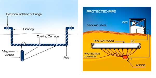
Corrosion is constantly attempting to degrade the performance of metal pipelines. The corrosion can be from dissimilar metals (galvanic corrosion), stray current corrosion from unintended sources of electricity, simple corrosion of similar metals (with varying anodic/cathodic sites), microbial induced corrosion and there are lesser-known types of corrosion.
Cathodic Protection Systems
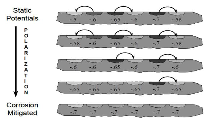
To prevent simple corrosion and galvanic corrosion, owners of metal pipelines will often send an electrical field through the pipeline equalizing the electrical potential for all sites (this is commonly referred to as a cathodic protection system) that dramatically reduces the effects of corrosion. Owners will also coat the metal pipelines to reduce the cost of electricity needed to protect the pipeline.
The Role of Isolation within CP Systems
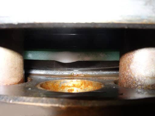
To further reduce the cost of electricity to protect the pipeline and to keep the electrical field to an effective level, isolation is often used in the form of flange isolation kits or monolithic isolation joints. Both products accomplish the same task, but flange isolation kits (FIKs) are predominately found in above ground installations while monolithic isolation joints (MIJs) are commonly found below ground. The terminology can change a bit regionally, but names like flange insulating kits, iso-kits, electrical isolation gaskets are often used to describe flange isolation kits and iso-joint, iso-block, monobloc, monoblock or insulating joint are all synonymous with monolithic isolation joints. Both FIKs and MIJs will stop the electrical flow through the pipeline and serve to keep the electricity in the areas that the pipeline owner wanted to protect. FIKs and MIJs break the metallic path in the pipeline and optimize the protection of the pipeline. Because they break the metallic path, they also stop stray current up to significant voltages. Breaking the metallic path as a function of an FIK or MIJ is very important because it will stop the electrochemical reaction between dissimilar metals. Pipelines will typically have valves, compressors, pumps, meters, pig launchers, etc. that are not made of the exact metallurgy as the pipeline itself. This difference in metallurgy brings with it differing potentials in the metals. With differing potentials and an electrolyte, the pipeline and the component are ripe to endure galvanic corrosion. By simply inserting a flange isolation kit (FIK), the metallic path between the component and the pipeline is eliminated and galvanic corrosion is then mitigated.
Microbial Induced Corrosion
When an FIK or MIJ is made to the pipe bore, this can dramatically reduce microbial induced corrosion (MIC) issues. Microbe colonies will build when there is an area to hold media such as a gap between flanges. If the FIK or MIJ is made to the pipe bore, the gap is eliminated and the potential for microbial colonies to grow is dramatically reduced.
There are adjacent benefits to using FIKs and MIJs in that by decreasing the amount of electricity needed to protect a pipeline, owners will likely see reduced issues with coating disbondment, and hydrogen induced corrosion. Both of which can be caused by higher levels of electrical flow through the pipeline.
Fire Safe Isolation Kits
There are many types of flange isolation kits and monolithic isolation joints on the market today. It is recommended that if the pipeline is carrying a flammable material that a fire safe flange isolation kit be used. If chemicals are added to the media to reduce microbial colonies from forming, to act as surfactants, to reduce iron sulfide build-up or for any other reason or if chemicals such as hydrogen sulfide are part of the media stream, it is important that the isolation kit is chemically compatible with the chemicals being used.
Role of Isolation Gasket on Emissions
Today, many companies are attempting to achieve greenhouse gas emission reduction goals. If the pipeline is part of that effort, it is recommended that glass reinforced epoxy (GRE) based isolation gaskets and phenolic isolation gaskets BE AVOIDED as these materials are permeable. It is also recommended that when an isolation product is used (either flange isolation kit or monolithic isolation joint), that a pipeline decoupler also be used to mitigate stray current or lightning effects that are beyond the capabilities of the isolation kit or joint.
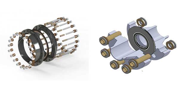
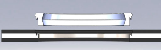
A common flange isolation kit will consist of an isolating gasket, an isolating sleeve and isolating washers (preferably fully coated and encapsulated stainless steel washers).
Typical flange isolation kit:
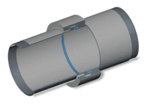
Typical monolithic isolation joint:
Introduction
Emissions, often referred to as Greenhouse gases (GHG) have been identified as a contributing factor in climate change. Climate change is one of the worlds more pressing challenges.
*Approximately 1-3% of methane leakage is the result of leaks in equipment intentional pressure release practices, or accidental releases during normal transportation, storage, and distribution activities.
Emissions is defined as the production and discharge of something, especially gas or radiation. In this instance we are talking about the production of unwanted gases often referred to as Greenhouse gases (GHG) that have been identified as a contributing factor in climate change. Climate change is one of the world’s more pressing challenges. Manmade carbon gas emissions total over 29 GT(gigatons) annually. To meet a 2° target according to the Paris Agreement, 15 GT of CO2 must be eliminated.
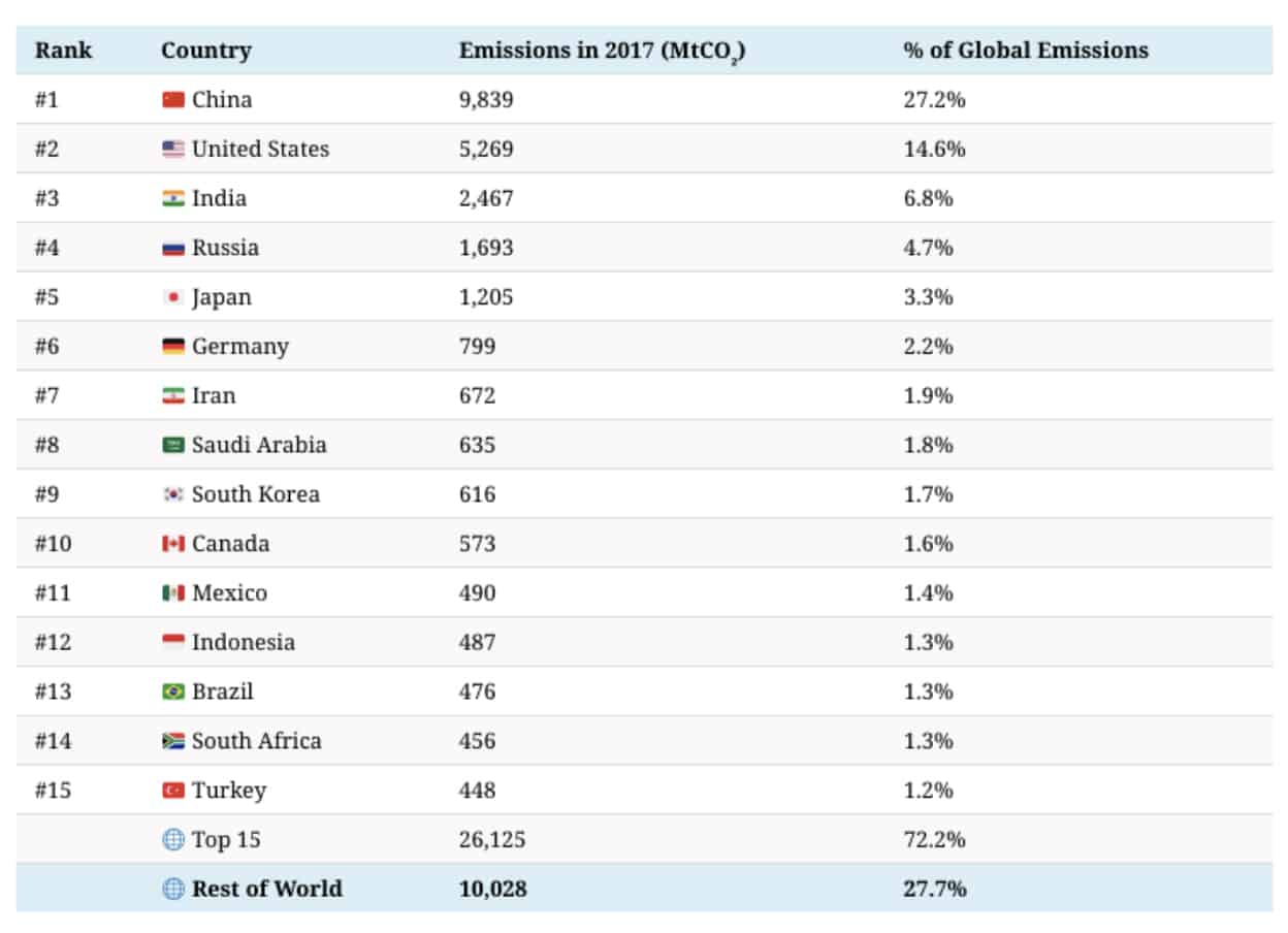
Fugitive emissions (unintentional production and discharge) account for 5.2% of all Greenhouse Gas Emissions according to the World Resources Institute, 2017. Sealing products that are extremely tight sealing are necessary to assist in the reduction of Greenhouse Gas Emissions globally.
Table of Contents
What are Pipeline Emissions?
How do we Measure Emissions?
Methods for Measuring Emissions
Pipeline Greenhouse Gases
How are GHG (Greenhouse Gas) Emissions Measured?
Greenhouse Gas Emissions by Country 2017
What is the Cause of Emissions or Poor Sealability?
Importance of Installing a Flange Isolation Kit (FIK) Correctly
How can do you Improve Pipeline Emissions?
Leakage Rates of Isolation Gaskets Vs a Spiral Wound Gasket
What are the Current Emission Standards in NA and Globally?
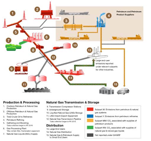
Which Sections of Oil and Gas Processing are Under Requirements by the EPA to Adhere to Emissions Standards?
Basics of Sealing
Gasket Load on Insulation Gaskets
Installing an FIK Gasket
What are Pipeline Emissions?
Emissions are the constant loss of product from within a pipe through and/or around a sealing element. Emissions are directly correlated to the sealability of a gasket or sealing product. It has been stated that “all gaskets leak”, but what is acceptable and unacceptable? Many companies are creating mandates to reduce GreenHouse Gas Emissions (GHG Emissions) to reduce the footprint for greenhouse gases and the EPA has strict standards when it comes to emissions for the oil and gas process. The creation of these requirements can now make a gasket that was once acceptable for emissions no longer acceptable.
Emissions today may not have been emissions in the past. As sensing technology has gotten better and the world has become more environmentally conscious, stricter and stricter requirements have been put in place. Chemicals that are injurious to the environment are often labelled as VOCs and HAPs.
"Volatile organic compounds (VOC) means any compound of carbon, excluding carbon monoxide, carbon dioxide, carbonic acid, metallic carbides or carbonates, and ammonium carbonate, which participates in atmospheric photochemical reactions. Source EPA.
HAPS are Hazardous Air Pollutants, also known as toxic air pollutants or air toxics, are those pollutants that are known or suspected to cause cancer or other serious health effects, such as reproductive effects or birth defects, or adverse environmental effects. EPA is working with state, local, and tribal governments to reduce air emissions of 187 toxic air pollutants to the environment.
Emissions can be measured in many different ways. Emissions measurement is the process of measuring the amount of pollutants, in a gaseous or particulate form, being emitted to the air from a specific source, such as an industrial process.
Measurements of emissions can be used to understand the relative importance of a given source compared to other sources and in developing emissions inventories.
Government or industry personnel use emissions measurements to assess the performance of control strategies. The gas stream can be measured before and after a pollution control device to determine how efficiently it captures pollutants. Emission measurements also are used to determine compliance with regulations limiting the amount of pollution that a source may emit.
Measurements can be taken over a short time period (e.g., hours), often referred to as a source test, or with methods that measure on a continuous basis, often called continuous emissions monitoring. Either way, it is important obtain data from samples that are representative of the emission stream using methods that are reliable.
There is something else that is an unwanted type of emission and it is called Greenhouse Gas Emissions. Greenhouse gases trap heat and make the planet warmer. Human activities are responsible for almost all of the increase in greenhouse gases in the atmosphere over the last 150 years.1 The largest source of greenhouse gas emissions from human activities in the United States is from burning fossil fuels for electricity, heat, and transportation.
How are GHG (Greenhouse Gas) Emissions Measured?
There are many methods such as FID, FTIR, NDIR, airplane LIDAR, optical gas imaging, Aerostat Aloft Platforms, Radial Plume Mapping and Eddy Covariance Methods.
In a global effort to become less reliant on fossil fuels and more reliant on clean energy, hydrogen is and has been used as an alternative fuel source. Hydrogen is the smallest known molecule, so sealing it is crucial especially since it has low ignition energy requirements and has high combustive energy properties. Tight emission control of this element can be achieved through the use of non-permeable gasketing solutions and proper installation practices.
What is the Cause - Emissions or Poor Sealability?
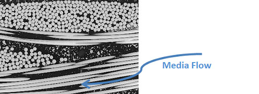
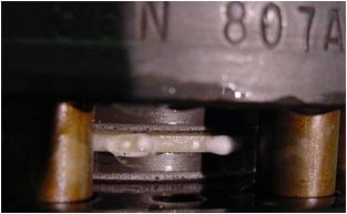
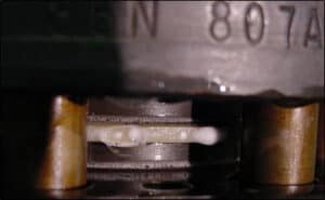
Through research, we have found that one of the items that is supposed to keep product within the piping systems can actually allow material to escape into the atmosphere...the isolation gasket or insulating gasket! Most isolation gaskets are produced of some time of Glass Reinforced Epoxy (GRE). The glass in the epoxy matrix is a straight rod (similar to a straw) and media (especially gases) can follow that straight path and escape into the atmosphere.
This is 300psig Nitrogen at ambient temperature. Similar examples have been witnessed with hydrocarbon gases. The thing to note here is that the example in the picture was in a test lab with ideal flange conditions and proper bolt load. With less than ideal flange conditions and improperly torqued bolts, the permeation and emissions can be much, much worse!
Importance of Installing a Flange Isolation Kit (FIK) Correctly
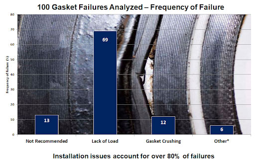
Another cause of emissions or poor sealability can be poor installation. Over 80% of gasket failures are due to improper installation practices or improper equipment conditions.
How do you Improve Pipeline Emissions?
One of the answers lies in two patented solution from GPT….The VCS-ID gasket and the EVOLUTION Isolating Gasket. The VCS-ID gasket is constructed of GRE and a 316SS core, but a PTFE inside diameter (ID) seal prevents any media from ever getting to the GRE. The PTFE immediately seals the pipe bore and is extremely chemically compatible.
The EVOLUTION gasket on the other hand eliminates GRE totally from the design as well as benefiting from the addition of the PTFE inside diameter (ID). Resulting in unparalleled sealing tightness performance, ideal for emission reduction in pipeline connections.
Emissions can worsen as flanges get larger due to flange rotation. The VCS-ID reduces this issue by instituting a dual seal design for isolation gaskets 6” NPS (nominal pipe size) and larger. The Secondary seal is in an outboard location.
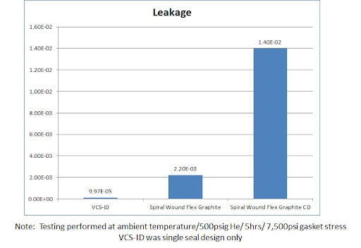
Leakage Rates of Isolation Gaskets vs a Spiral Wound Gasket
Note: Testing Performed at ambient temperature/500psig He /5hrs / 7,500psi gasket stress VCS-ID™ was single design only
Another major improvement to emissions and sealing is to participate in GPT’s GFIT program, GPT Flange Isolation Training. This program certifies participants in the proper alignment of flanges, the correct method of evaluating flange faces, tried and true torquing techniques, inspection procedures and provides “hands on” elements for both installation and isolation gasket testing.
What are the Current Emission Standards in NA and Globally?
According to the clean air act, all new oil storage tanks that come into service after April 12, 2013, must have VOC controls within 60 days of service or by April 15, 2014 (whichever is later). Tanks that were in service as of April 12, 2013, must have VOC controls no later than April 15, 2015. Tanks subject to existing federal or state CAA permits are exempt if they emit less than 6 tons of VOC per year with controls. Owners/Operators have the option of either reducing the VOC emissions at a tank by 95% or meeting an alternative emissions limit if the owner or operator can make a demonstration that the tank emits less than 4 tons of VOC per year without controls.
Which Sections of Oil and Gas Processing are Under Requirements by the EPA to Adhere to Emissions Standards?
Have you ever installed an isolating kit in a pipeline, successfully tested for electrical isolation, but later failed isolation following a hydrotest?
What part does load play with emissions and sealabilty?
Proper compression of the gasket is extremely important, but can be usurped by poor flange conditions or installation practices. We recommend using an installation procedure like this and making sure that flanges are aligned.
Is there training that can be taking to improve sealability for our products?
There are two training programs that GPT offers. One is the GFIT (GPT Flange Installation Training) program and the other is a Level I, II and III training program that teaches more about product selection, design and use.
Are there pitfalls that I can avoid regarding emissions and sealability?
The common issue that we see is the use of homogeneous GRE products in gaseous applications and then concern when they initiate some type of leak detection. It is quite common for these types of products to permeate (especially under higher pressure), so for gaseous applications, we recommend the use of a PTFE ID sealed isolation product.
Can liquid permeate through my GRE gaskets?
Surprisingly, the answer is yes. With high pressure and time, the media can permeate through the GRE. Another reason we recommend a PTFE ID seal to prevent any media contact with the GRE.
Basics of Sealing
Sealing capability is typically reliant upon two seemingly simple factors: gasket permeability and gasket load. Gasket permeability can be deceiving because many gaseous mediums are invisible and unless a person can acoustically hear the leakage or see a colored gas emitting from the gasket, the gasket has often been deemed “sealing”. As technology and requirements have become more strict, we now know the above not to be true. A gasket can still be leaking if a person is unable to see or hear leakage. Many companies now use a soapy water mixture to place on the gasket surface and gases leaking through the gasket or around the gasket will be displayed as bubbles.
Also, many companies now use much more sophisticated methods to assess leakage. The companies will use infrared technology to see temperature changes in the air caused by leaking gases. Companies will also use gas analyzers, helicopters, unmanned aerial vehicles, solar powered sensors (SPods) and chromatographs as well as other means.
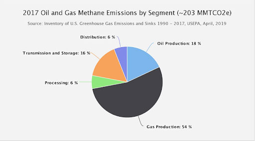
There are also methods used to estimate fugitive methane emissions in transmission pipelines.
Gasket Load on Insulation Gaskets
Gasket load can be as complex as emission monitoring. Gaskets typically have a psi (pounds per square inch) or a kPa (1 kPa is approximately the pressure exerted by a 10-g mass resting on a 1-cm2 area. 101.3 kPa = 1 atm.) minimum requirement and a maximum allowable limit (note the maximum can change if the gasket is subjected to exposure in a liquid). Let’s say a gasket has a minimum gasket load (or stress) of 3,000 psi or 20,684 kPa and a maximum gasket load (or stress) of 15,000 psi or 103,421 kPa. This means the gasket will start to effect an acceptable seal at the minimum stress and can begin to break down at the maximum stress.
A “good” load on this gasket might be around 10,000psi or 68,948 kPa. This allows for some bolt stress relaxation and gasket relaxation to occur before leakage or gasket failure. Now how does one achieve the proper gasket stress? The answer is in torquing the bolts to the proper level to achieve the required gasket stress. This is where it can begin to get “complex”. The proper gasket stress will depend on many variables (reused nuts/bolts, rusty nuts/bolts, calibrated torque wrench, aligned flanges, proper flange face RMS (root mean square) finish (should be concentric or spiral grooves), type of lubricant used (if any), type and number of washers used (should be two washers).
Even the orientation of the nuts can be a factor (printed side of the nut should face away from the washers). There are other factors that should be taken into account, but these are the primary factors. Much has been written on this subject and a good book to read is John Bickford’s book on “Gaskets and Gaskets Joints.'
Installing an FIK Gasket
Here is a video that will help with the installation of an isolated kit in a flange. Installing an isolation kit is different than installing a standard gasket in even the same flange.
Our Recommendation
EVOLUTION is a superior choice for controlling emissions of methane, ethane, carbon dioxide, carbon monoxide (greenhouse gases) and hydrogen as well as many other chemicals that need to be contained in piping systems.
Introduction
Corrosion is a natural process where refined materials react with their environment, and revert to a more chemically-stable form. Below we discuss some of the most common topics and questions surrounding corrosion.
Table of Contents
Basics of Corrosion
The Galvanic Series
Cathodic Protection Design
Pipeline Corrosion Protection with Isolation
What is External and Internal Corrosion?
What was the Impact of Pipeline Incidents?
Why do we put Pipes Below Grade? What Challenges Does it Present?
How does Electrical Isolation help Prevent Corrosion?
What Applications Require Electrical Isolation?
What are Common Causes for Isolation Failures?
Basics of Corrosion
Corrosion is a constant force in industries from Oil & Gas production, Maritime, to construction of highways, bridges, pipelines, & any underground systems. Corrosion is a natural process where refined materials react with their environment, and revert to a more chemically-stable form. The rate of corrosion is dependent on a number of environmental variables, but for corrosion to occur four basic elements are required (Anode, Cathode, Metallic Path, and Electrolyte).
In the fight against corrosion, integrity engineers focus on removing the presence of one or more of these basic elements. The first defense against corrosion is a coating system which helps to protect the asset from the surrounding electrolyte. Coatings are typically used as a barrier coating, protecting the substrate from contact with the Electrolyte. In addition to serving as a barrier, some coatings also use inhibitive, or sacrificial pigments, causing passivation, or a sacrificial anode to form at any Coating Holidays or defects.
Integrity engineers must also utilize cathodic protection (impressed or passive) to protect assets, as coatings can be damaged, which can amplify corrosion locally at the defect (Coating Holiday, cracking, etc.). Cathodic protection systems combat corrosion by converting all of the anodic (active) sites on the metal surface of an asset to cathodic (passive) sites by supplying electrical current (or free electrons) from an alternate source to equalize the potential on the surface of the metal structure (left).
The Galvanic Series
Materials are listed from most Noble (passive), to most electronegative (active) in the Galvanic series. In reference to the below graphic, Magnesium is the most active. When two metals are coupled, the more active will share electrons with the more noble material causing an oxidation reaction (rust) at the electronegative material, and a reduction reaction at the more electropositive (noble) material.
Cathodic Protection Design
CP does not eliminate corrosion, but actually transfers corrosion current from the protected structure (asset) to the cathodic protection anode. This is the case in Galvanic (Sacrificial) anode systems, and impressed current system.
A sacrificial anode system is easily installed, requires no external electricity, and minimal right-of-way cost. The limitations of sacrificial anodes are current output, require anodes to be replaced once an anode has been spent / consumed, and a higher cost per unit ampere than impressed current. Based on the above characteristics, galvanic systems are used in specific applications (offshore, within vessels, or in an area with many other metallic structures). Galvanic anodes are commonly used in combination with impressed current systems at problem/ repair areas, shorted casings, cathodic interference / stray current discharge points, areas influenced by electrical shielding, and locations with significant coating damage.
Impressed current systems are comprised of an external power source and anodes. The power source (rectifier) forces current to flow from the anode to the structure to through the electrolyte.
Pipeline Corrosion Protection with Isolation
Pipe and the metallic pipeline components are supplied coated (Valves, Fittings, etc.). Following welding, and inspection field applied epoxies are used to cover exposed weld bevels.
What is Pipeline Isolation?
In metallic pipelines, corrosion is the constant attempt by nature to reduce pipelines to their original oxide state. It is an electrochemical reaction that has four parts: anode, cathode, metallic path and electrolyte. Flange isolation and joint isolation are a means of preventing electrochemical reactions from occurring between two dissimilar metals by breaking the metallic path, or preventing the current in a cathodic protection (CP) from traveling beyond the area intended to be protected by the CP system. ;
In addition, Cathodic protection (CP) systems are used to supply extra electrons causing the asset to be a passive location or a cathode. In order to control what is protected by these electrons, isolation is used as the ‘bookends’ of a CP system. Isolation will allow you to protect specific assets, and eliminate any dissimilar metals connection. An example would be a pipeline coming into a compressor station, the role of the CP system is to protect the pipeline, but not the compressor station. Isolation would be used on either side of the compressor station to avoid the large metallic compressor station draining the CP current.
What is External Corrosion?
External corrosion occurs due to environmental conditions on the exterior surface of the steel pipe that can cause an electrochemical interaction between the exterior of the pipeline and the soil, air, or water surrounding it. Galvanic and atmospheric corrosion are common types of external corrosion.
What is Internal Corrosion?
Internal corrosion occurs due to a chemical attack on the interior surface of a steel pipe from the products transported in the pipe. This can be from either the commodity transported, or from other materials carried along with the commodity, such as water, hydrogen sulfide, and carbon dioxide.
Is Natural Gas Corrosive?
Natural Gas can mean gas containing methane, Ethane, H2S, water, and COS, and other components. Natural Gas will be corrosive because of the H2S and water. Commercial Natural Gas is treated, and it is no longer corrosive.
What is PHMSA?
PHMSA is a portion of the DOT. PHMSA is the Pipeline and Hazardous Materials Safety Administration. Est. 1970.
How Many Pipeline Failures are the Result of Corrosion?
Data shows that from 1998-2017 approximately 18% of pipeline incidents on average were caused by corrosion, learn more here.
What was the Impact of Pipeline Incidents?
Why do we Put Pipes Below Grade? What Challenges Does it Present?
While there are above ground pipelines, most notably the Trans-Alaska Pipeline System (TAPS). The significant majority of pipelines are buried. Pipelines are often located below grade due to permitting requirements in order to minimize the impact to the surrounding communities by concealing it from view. Pipelines will come above ground for pump stations, valves, and other equipment requiring access.
Locating pipelines below grade introduces the pipeline into constant contact with an Electrolyte, one of the four elements needed for a corrosion cell. The first line of defense is a Barrier Coating, which creates a barrier between the Electrolyte and the metallic structure.
How Does Electrical Isolation Help Prevent Corrosion?
Electrical Isolation in a pipeline system is achieved by installing Flange Isolation Kits (FIKs), or Monolithic Isolation Joints (MIJs) in line to separate equipment or pipeline segments. FIKs & MIJs utilize materials with resistance to electrical current in order to block the transfer of electrons, effectively eliminating the metallic path, one of the four elements needed for a corrosion cell.
What Applications Require Electrical Isolation?
Electrical Isolation is used to break up pipeline segments to optimize current output from rectifiers in Impressed current cathodic protection systems. It is advantageous to break up long pipeline runs with isolation to improve efficiency, and minimize the impact of maintenance or repair on the pipeline.
Electrical Isolation is also used to prevent interference or damage to electronics, which may be found in valves, sensors, compressor stations, and other equipment.
Electrical Isolation should also be used in the presence of any dissimilar metal connection to prevent a galvanic coupling.
What are Common Causes for Isolation Failures?
Failure of electrical isolation gasket, joint, or union can be caused by environmental factors, mechanical forces exerted on the pipeline system, or improper installation. The likelihood of failure due to environmental factors can be controlled by the materials used.
A variety of materials are used to provide electrical isolation within a pipeline systems. The different materials have different characteristics which impact their efficacy (Electrical Resistance, Water absorption, Dielectric Strength, Permeability, Temperature range, Chemical Resistance, Compressive strength).
Electrical resistance is a measure of how well a material resists electrical current.
Isolation materials which have a high water absorption will be impacted by humidity, rainwater, and snowmelt. The moisture within the isolation material will cause a significant reduction in the electrical resistance. In conditions with temperatures fluctuating from above to below freezing also have the potential for cracking of the isolation material.
Introduction
A seal assists in connecting systems or mechanisms together by preventing leakage, containing pressure or excluding contamination.
A flange Isolation(insulation) gasket used in conjunction with an isolation kit (washers & sleeves), does all these things, but also provides electrical isolation, reducing or mitigating the build up of corrosion.
Table of Contents
1. What is Pipeline Sealing?
2. Why do Pipeline Sealings Fail?
3. Changing Oil and Pipeline Gas Conditions
4. GRE Isolation Gasket Pitfalls
Why do Pipeline Seals Fail?
Over 80% of leakage or isolation issues are from poor installation.
Installation
The most common pitfalls for a good seal is installation. Over 80% of leakage or isolation issues are from poor installation although we see this potentially changing in the future due to the fact that oil and gas companies are becoming more concerned about greenhouse gas emissions. As levels are put in place as maximum leakage levels, gaskets that were once deemed acceptable from a sealing level would potentially be labelled as “leakers” requiring a selection of a new type of isolation gasket. This could be entirely independent of the method of installation.
Most likely it has to do with installation. Over 80% of failures are attributed to installation issues. The most common installation issue is not creating a large enough gap for the gasket to EASILY be inserted between the flanges. Flanges should be aligned prior to the insertion of the gasket. The second most common cause of failure is improper application of torque. Make sure to use the manufacturer’s recommended torque, to install in three even increments of 33%, 66% and 100% of the recommended torque. Also, be sure to use a “star” pattern when torquing. A few other quick checks would be to make sure you are not using a lubricant that contains metallic particles, make sure that your washers are not “reversed” the metal washer must be the washer contacting the nut and make sure the nut “flat” is toward the washer, not the nut side that has raised printing.
Changing Oil and Gas Pipeline Conditions
Pipeline conditions have been changing over the last 50 years. More and more aggressive chemicals are finding their way into the media stream (hydrogen sulfide, steam, carbon dioxide, carbon monoxide, etc.). Temperatures have risen, pressures have risen and we are seeing a trend towards larger diameter pipelines which can be much more difficult to properly install and seal.
As a world leader in the manufacture of isolation products coupled with a significant engineering team, GPT has discovered that the changes in our pipelines are affecting traditionally used isolation gaskets. The combination of higher temperatures and higher pressures can cause blowouts of GRE based materials that do not have a glass transition temperature high enough for the operating temperature. Chemical combinations of sour gas can chemically attack GRE. What can compound this issue is the propensity for GRE to all media to permeate into the body of the gasket. This can cause a loss of volume, mass and density of the GRE. This in turn, can reduce bolt load causing greater leakage and potential for blowout.
Changes in the workforce have not helped pipelines to become better sealing either. The 5 year average for pipeline incidents according to PHMSA data shows that there have been an average of 666 incidents for the 5 year period from 2014 through 2018, however the 5 year average from 1999-2003 was only 474 incidents. Some likely reasons are that millenials are changing jobs at a much greater rate than baby boomers. LinkedIn has studied 500 million users over a 20 year period and has found that a millennial will change jobs an average of four times their first 10 years out of school. This means that the likelihood of a pipefitter being a long term, highly trained individual is diminished. Since more than 80% of gasket failures occur due to poor installation, a lesser trained workforce will not benefit the situation.
GRE Isolation Gasket Pitfalls
Unfortunately, Glass Reinforced Epoxy (GRE) the material that most isolation gaskets are constructed of, has significant permeation (see photo to the right). This is a GRE gasket (G10 in this case) with 300psi Nitrogen gas. Snoop™ leak detector has been applied and it is evident that the nitrogen gas is easily passing through the gasket. Carbon monoxide and carbon dioxide would perform similarly as would ethane and methane.
Oddly enough, isolation gasket manufacturers for years knew that the gases permeated through the GRE, but attempted to develop ways to use the media to drive through the body of the gasket and push the seal against the flange creating a seal (often called a “self energizing seal” and sometimes called a “leak to seal” design).
Fortunately, GPT has developed a patented method for sealing the media before it ever gets to the GRE. The product is called VCS-ID and has a PTFE inside diameter (ID) seal (see image).
The PTFE ID seal is machined to lock into the GRE and the 316SS metal core so that it is unable to come.
When I put “Snoop” on my gasket in a flange, bubbles appear very quickly and easily. Can I put more load on the gasket and stop the leak?
Probably not if you are using a glass reinforced epoxy (GRE) gasket. It is much more difficult to compress a GRE gasket as compared to a fiber or PTFE gasket. GRE unfortunately is prone to “permeation” and what you will often be seeing is permeation through the gasket rather than leakage past the seal. The solution to this is VCS-ID or Evolution which has a PTFE seal that stops the media before it gets to the GRE.
What is the best sealing isolation gasket?
From our lab testing, the Evolution gasket is the best available isolation gasket for an extremely tight seal. Typical sealability values are in the range of 1x10⁻⁹ Pa.m3/s/mm helium in ambient temperature testing. Most other isolation gaskets are in the 1x10⁻⁴ range.
We use certain technically necessary cookies that are required to make our site work properly and enable core functionality, such as security, network management and accessibility. We also use analytics cookies to help us improve our website by collecting and reporting information on how you use it. The cookies collect information in a way that does not directly identify anyone. By clicking ACCEPT you agree to the storing of analytics cookies on your device to analyze site usage.
This website uses cookies to improve your experience while you navigate through the website. Out of these, the cookies that are categorized as necessary are stored on your browser as they are essential for the working of basic functionalities of the website. We also use third-party cookies that help us analyze and understand how you use this website. These cookies will be stored in your browser only with your consent. You also have the option to opt-out of these cookies. But opting out of some of these cookies may affect your browsing experience.
Necessary cookies are absolutely essential for the website to function properly. These cookies ensure basic functionalities and security features of the website, anonymously.
Cookie
Duration
Description
cookielawinfo-checkbox-analytics
11 months
This cookie is set by GDPR Cookie Consent plugin. The cookie is used to store the user consent for the cookies in the category "Analytics".
cookielawinfo-checkbox-functional
11 months
The cookie is set by GDPR cookie consent to record the user consent for the cookies in the category "Functional".
cookielawinfo-checkbox-necessary
11 months
This cookie is set by GDPR Cookie Consent plugin. The cookies is used to store the user consent for the cookies in the category "Necessary".
cookielawinfo-checkbox-others
11 months
This cookie is set by GDPR Cookie Consent plugin. The cookie is used to store the user consent for the cookies in the category "Other.
cookielawinfo-checkbox-performance
11 months
This cookie is set by GDPR Cookie Consent plugin. The cookie is used to store the user consent for the cookies in the category "Performance".
viewed_cookie_policy
11 months
The cookie is set by the GDPR Cookie Consent plugin and is used to store whether or not user has consented to the use of cookies. It does not store any personal data.
Functional cookies help to perform certain functionalities like sharing the content of the website on social media platforms, collect feedbacks, and other third-party features.
Performance cookies are used to understand and analyze the key performance indexes of the website which helps in delivering a better user experience for the visitors.
Analytical cookies are used to understand how visitors interact with the website. These cookies help provide information on metrics the number of visitors, bounce rate, traffic source, etc.
Advertisement cookies are used to provide visitors with relevant ads and marketing campaigns. These cookies track visitors across websites and collect information to provide customized ads.